· Updated · FieldDojo Team · hvac · 10 min read
Duct Sizing for HVAC: The ASHRAE Equal Friction Method Explained
How to size supply and return ducts correctly using the equal friction method — the ASHRAE standard approach used by HVAC professionals.
Undersized ducts restrict airflow, cause pressure imbalances, and make systems work harder than they should. Oversized ducts waste materials and money. The ASHRAE equal friction method gets you to the right size systematically.
Verify before you build. Section numbers, table values, and demand factors change between code editions, and jurisdictions adopt them with local amendments. Treat this guide — and the app — as a calculation aid, not as the code book: confirm every number against the edition your authority having jurisdiction enforces. How FieldDojo validates its calculations.
What is the Equal Friction Method?
The equal friction method sizes ducts so that friction loss per unit length is equal throughout the duct system. The target is typically 0.08–0.10 in. wg per 100 feet of duct for residential work, and up to 0.10–0.15 in. wg/100 ft for commercial systems.
This approach:
- Balances the system naturally (less need for manual damper adjustment)
- Is straightforward to calculate
- Is recognized by ASHRAE fundamentals as the standard residential/light commercial method
It is also the core sizing approach behind ACCA Manual D, the residential duct design standard — the duct-side companion to the Manual J load calculation.
Step 1: Calculate the Heating or Cooling Load
Before sizing ducts, you need to know how much air each room requires. This comes from a Manual J load calculation, which accounts for:
- Room area and ceiling height (volume)
- Insulation R-values
- Window U-values and solar heat gain
- Infiltration rate
- Occupancy and internal gains
The output is BTU/hr (heating) or tons (cooling). From there, you calculate CFM (cubic feet per minute):
CFM = Sensible BTU/hr ÷ (1.1 × ΔT)Where ΔT is the temperature difference between supply air and room temperature (typically 20–25°F for heating, 15–20°F for cooling).
The load that goes into this equation is the sensible load — the part that changes air temperature. Manual J reports sensible and latent separately, and only the sensible portion drives airflow. Feed it a total cooling capacity and you will oversize every duct in the system by roughly 1 ÷ SHR.
Where that constant comes from: 0.075 lb/ft³ (standard air density) × 0.24 Btu/lb·°F (specific heat of air) × 60 min/hr = 1.08 at sea level. 1.1 is the rounding the trade has used for decades, and it is what the worked examples below use; FieldDojo’s app uses the exact 1.08. The 1.8% gap never changes a duct size — but if you compare a hand calculation here against the app and see a small difference, that is the whole of it. See the altitude note below before using either value at elevation.
Example: 12,000 BTU/hr sensible cooling load, ΔT = 20°F:
CFM = 12,000 ÷ (1.1 × 20) = 545 CFMStep 2: Size the Main Trunk
The main trunk carries total system CFM. Using an ASHRAE duct sizing chart (or friction chart) at your target friction rate:
At 0.10 in. wg/100 ft:
- 500 CFM → approximately 10” round duct
- 1,000 CFM → approximately 14” round duct
- 2,000 CFM → approximately 18” round duct
For rectangular ducts, use equivalent diameter:
De = 1.30 × (a × b)^0.625 / (a + b)^0.25Where a and b are duct dimensions in inches.
Step 3: Size Branch Ducts
Each branch serves a specific room. Size each branch based on its CFM requirement at the same target friction rate.
Example branch run:
- Room load: 6,000 BTU/hr sensible cooling
- CFM needed: 6,000 ÷ (1.1 × 20) = 273 CFM
- At 0.10 in. wg/100 ft: approximately 8” round duct
Step 4: Check Velocity
Even after sizing for friction, verify duct velocity is acceptable:
- Supply ducts (main trunk): 600–900 FPM maximum for residential (noise threshold)
- Supply ducts (branches): 400–600 FPM
- Return ducts: 400–600 FPM
Velocity formula:
FPM = CFM ÷ Duct Area (sq ft)A 10” round duct has area = π × (5/12)² = 0.545 sq ft. At 500 CFM: 500 ÷ 0.545 = 917 FPM — slightly over the residential limit. Upsize to 12” (0.785 sq ft = 637 FPM ✓).
Worked Example: Sizing a Trunk and Two Branches
Say you’re adding a small two-room system — an office and a bedroom over a garage. The Manual J puts each room at 6,000 BTU/hr sensible cooling. Supply ΔT is 20°F, and the target friction rate is 0.10 in. wg/100 ft. Here’s the full sequence.
Step 1 — Convert loads to airflow.
Each branch:  6,000 ÷ (1.1 × 20) = 273 CFM
Trunk:       12,000 ÷ (1.1 × 20) = 545 CFM
The trunk carries the sum of everything downstream of it — both rooms.
Step 2 — First pass from the friction chart.
Reading the chart at 0.10 in. wg/100 ft:
- Trunk at 545 CFM → approximately 10” round
- Each branch at 273 CFM → approximately 8” round
Step 3 — Velocity-check the trunk.
A 10” round duct has area = π × (5/12)² = 0.545 sq ft.
545 ÷ 0.545 = 1,000 FPMThat’s over the 900 FPM residential noise threshold. Upsize to 12” (0.785 sq ft):
545 ÷ 0.785 = 694 FPM ✓694 FPM sits inside the 600–900 FPM trunk band. Trunk: 12” round.
Step 4 — Velocity-check the branches.
An 8” round duct has area = π × (4/12)² = 0.349 sq ft.
273 ÷ 0.349 = 782 FPMAbove the 400–600 FPM branch guideline — that duct will be audible in a bedroom. Upsize to 10” (0.545 sq ft):
273 ÷ 0.545 = 501 FPM ✓Branches: 10” round each.
Step 5 — Account for fittings.
Friction rate is per 100 feet of equivalent length, not just straight duct. A 90° elbow can add 5–20 feet of equivalent length, so a branch with 25 ft of straight run and two elbows behaves like anywhere from 35 to 65 ft of duct. Count the fittings before you trust the pressure math.
The result:
| Run | CFM | Friction-chart size | After velocity check |
|---|---|---|---|
| Trunk | 545 | ~10” round | 12” round |
| Branch A | 273 | ~8” round | 10” round |
| Branch B | 273 | ~8” round | 10” round |
Notice that velocity — not friction — set every final size in this example. That’s common on residential work, where the noise ceiling is low. Run both checks every time; the friction chart alone isn’t the answer.
Round vs Rectangular Duct: Which Should You Use?
Round duct moves air more efficiently: a circle encloses the most area with the least perimeter, so for the same airflow there’s less metal dragging on the airstream. Rectangular duct exists because buildings are rectangular — it fits where round won’t. The trade-offs:
| Trade-off | Round duct | Rectangular duct |
|---|---|---|
| Friction loss for the same airflow | Lower — least surface area per CFM | Higher, and it gets worse as the shape flattens |
| Fit in tight spaces | Needs full circular clearance | Fits shallow joist bays, soffits, and ceiling plenums |
| Material for the same capacity | Less sheet metal | More metal, especially at high aspect ratios |
| Sealing | Fewer seams to seal | More longitudinal seams and corner joints |
| Noise | Quieter at a given velocity | Large flat panels can drum at trunk velocities |
| Sizing | Read the diameter straight off the friction chart | Convert through equivalent diameter first |
When you do go rectangular, size it through the equivalent diameter formula from Step 2:
De = 1.30 × (a × b)^0.625 / (a + b)^0.25For the worked example above, suppose the 12” round trunk has to run flat inside a soffit. A 12” × 10” rectangular duct gives:
De = 1.30 × (12 × 10)^0.625 / (12 + 10)^0.25 ≈ 12"— an even swap for the 12” round trunk. Keep the aspect ratio as close to 1:1 as the space allows; the flatter the duct, the more friction and metal you pay for the same equivalent diameter.
What Are the Most Common Duct Sizing Mistakes?
1. Skipping the load calculation. Sizing ducts by rule of thumb (“1 ton per 400 sq ft”) without a proper Manual J leads to systems that can’t meet design conditions.
2. Ignoring fittings. Each elbow, tee, and transition adds friction. Account for equivalent lengths: a 90° elbow can add 5–20 feet of equivalent straight duct.
3. Undersizing returns. Return ducts are just as important as supply. Undersized returns create negative pressure in the living space, pulling air through gaps and leaks.
4. Using the wrong friction rate. 0.08–0.10 in. wg/100 ft is correct for most residential systems. Using 0.05 gives you oversized ducts; 0.15 gives undersized ones.
5. Forgetting altitude. Friction charts and velocity math assume standard air density — 0.075 lb/ft³ at sea level. At elevation the air is thinner, and sea-level chart values need a density correction. If you’re installing in Denver, don’t size like you’re in Houston.
Frequently Asked Questions
What size duct do I need for a 3-ton AC?
A 3-ton system delivers 36,000 BTU/hr of cooling. At a 20°F supply ΔT, that’s 36,000 ÷ (1.1 × 20) ≈ 1,636 CFM. On a friction chart at 0.10 in. wg/100 ft, that lands between the 14” round size (1,000 CFM) and the 18” size (2,000 CFM) — read the chart at your exact CFM, then check velocity.
What is the equal friction method?
The equal friction method sizes every duct in a system to the same friction loss per unit length — typically 0.08–0.10 in. wg per 100 ft for residential work. Because each run loses pressure at the same rate, the system largely balances itself. It’s the standard residential approach in ASHRAE fundamentals and ACCA Manual D.
How many CFM per ton of cooling?
About 400 CFM per ton — the residential design range is 350–450. One ton equals 12,000 BTU/hr of total capacity, but airflow is set by the sensible portion of that load, not the total. At a typical residential sensible heat ratio of 0.75 and a 20°F supply ΔT: (12,000 × 0.75) ÷ (1.1 × 20) ≈ 410 CFM. Running the total capacity through the sensible equation instead returns roughly 545 CFM and oversizes the ductwork. Use 350 CFM/ton in humid climates where more capacity goes to dehumidification, and up to 450 in dry ones.
What friction rate should I use for residential ductwork?
Target 0.08–0.10 in. wg per 100 ft for residential systems; commercial designs run up to 0.10–0.15. Going lower (0.05) oversizes ducts and wastes material; going higher (0.15) undersizes them and starves airflow. Whatever rate you pick, apply it to every trunk and branch — that’s what makes the friction “equal.”
How fast should air move through residential ducts?
Keep main supply trunks at 600–900 FPM maximum and branches and returns at 400–600 FPM — above that, ducts get audible. Check with FPM = CFM ÷ duct area in sq ft. If a duct passes the friction target but fails the velocity check, upsize one diameter and recheck.
Do I need a Manual J calculation before sizing ducts?
Yes. Duct sizes come from room-by-room CFM, and CFM comes from the load. An ACCA Manual J accounts for insulation, windows, infiltration, and internal gains. Square-footage rules of thumb typically land within 15–25% of a full Manual J on a simple single-story home — and can miss by 40% or more on anything unusual.
How FieldDojo Handles This
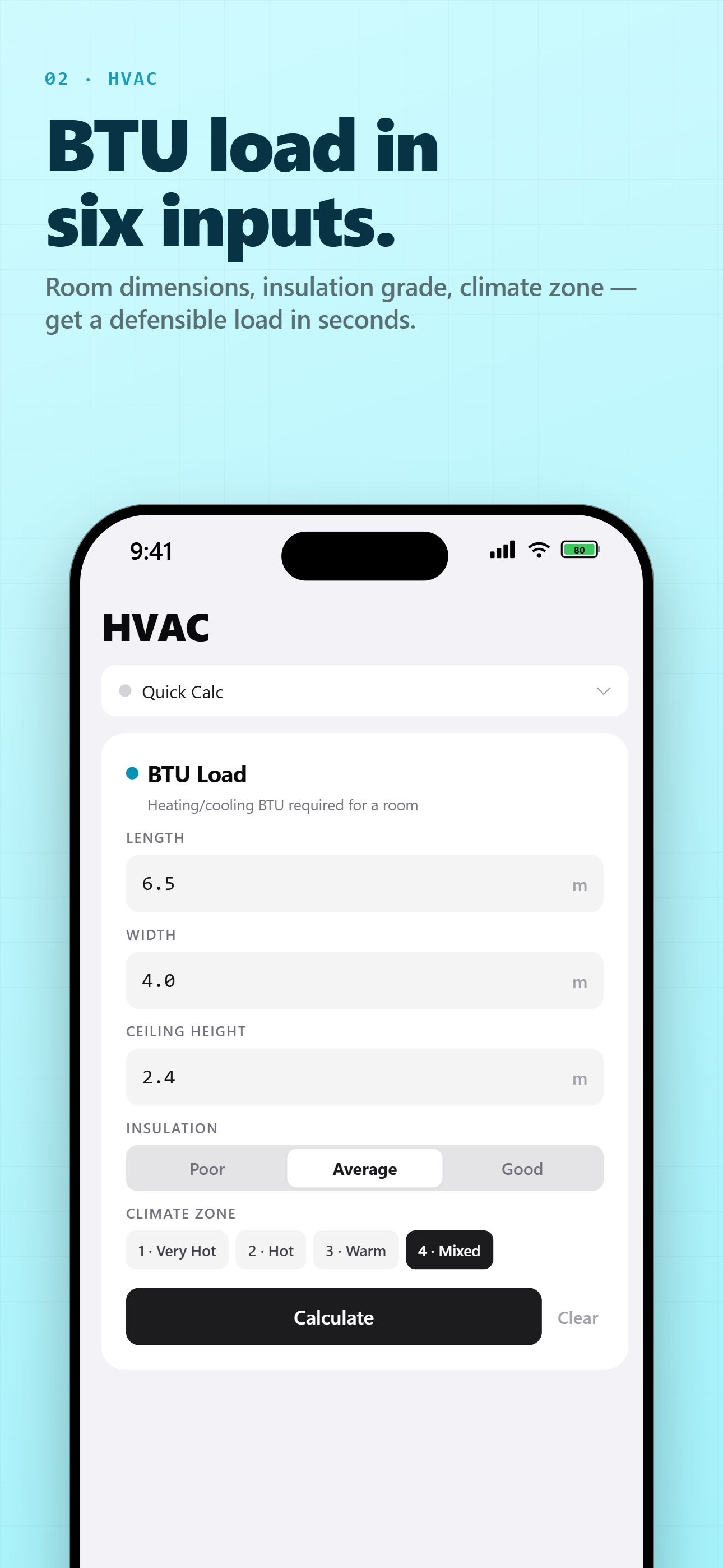
FieldDojo’s duct sizing calculator runs the same ASHRAE-based method described above: punch in the CFM and your target friction rate, and it returns the recommended round diameter with the resulting velocity right beside it — so the noise check happens on the same screen, not on a second pass. Every result carries its ASHRAE reference, and the BTU load and heat load calculators feed the same workflow, taking you from room dimensions to duct size without leaving the app.
Get FieldDojo on the App Store → or on Google Play → — free on both.
Related trade guides: