· Updated · FieldDojo Team · plumbing · 14 min read
Pipe Sizing for Plumbers: Water Supply, Drainage, and Gas Piping
How to size water supply pipes, drain/waste/vent systems, and gas piping correctly — with the IPC and NFPA 54 references behind each calculation.
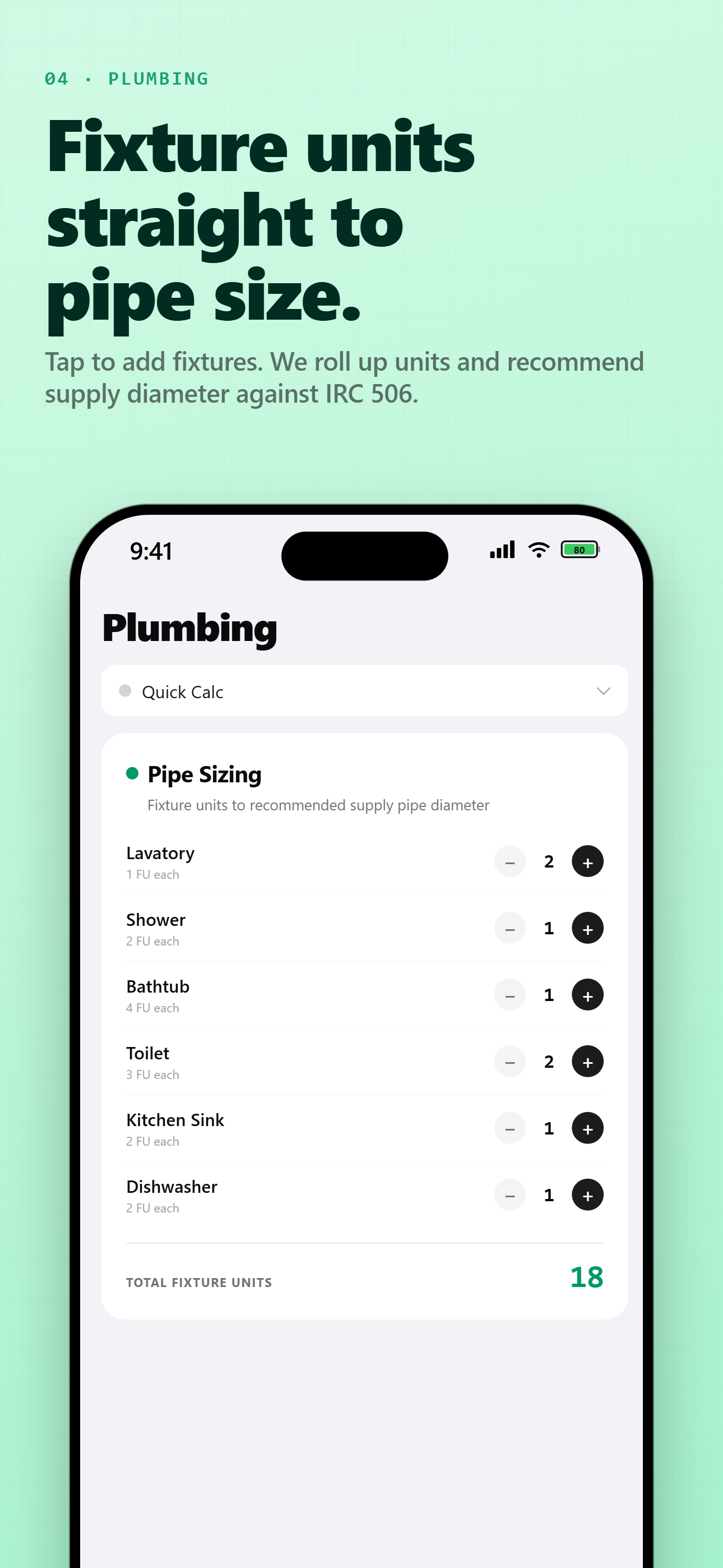
Pipe sizing is one of the most consequential calculations in plumbing. Too small and you get inadequate pressure and velocity. Too large and you waste material, lose velocity in drain lines, and create self-siphonage problems. Here’s how to get it right for the three main systems you’ll encounter — water supply, drainage, and fuel gas — plus a worked example for a two-bath house.
Verify before you build. Section numbers, table values, and demand factors change between code editions, and jurisdictions adopt them with local amendments. Treat this guide — and the app — as a calculation aid, not as the code book: confirm every number against the edition your authority having jurisdiction enforces. How FieldDojo validates its calculations.
Water Supply Pipe Sizing
Water supply sizing starts with demand — how much water the system needs to deliver simultaneously. The standard method counts Water Supply Fixture Units (WSFU), a weighting that accounts for how likely each fixture is to be running at any given moment.
Step 1: Count Fixture Units
Each fixture has an assigned WSFU value. These are the values FieldDojo uses, so the app and this page never disagree:
| Fixture | WSFU |
|---|---|
| Water closet (1.6 gpf, tank) | 2.2 |
| Hose bibb | 2.5 |
| Bathtub | 1.4 |
| Shower | 1.4 |
| Kitchen sink | 1.4 |
| Dishwasher | 1.4 |
| Clothes washer | 1.4 |
| Lavatory (bathroom sink) | 0.7 |
Source: IPC Table E103.3(2), 2021 edition, private (dwelling) occupancy, total-demand column — the edition FieldDojo’s tables encode. Confirm against the edition your jurisdiction has adopted.
The UPC and the IRC assign different numbers to the same fixtures, and a flush-valve water closet carries a much higher load than the tank-type fixture above. Whichever code your AHJ enforces, take the whole set from that one code — mixing values from two codes in one calculation produces a number that is not valid under either.
Add up the total WSFU for all fixtures served by a branch or the main.
Step 2: Size the Pipe
The rigorous route is two steps. First convert total WSFU to peak demand in GPM using the Hunter demand curve — the relationship is deliberately non-linear, because the more fixtures a system has the less likely they are all to run at once. Then size for that flow from a friction-loss table (IPC Table E103.3(3), which relates diameter to GPM and pressure loss per 100 ft) while staying inside the velocity limits: 5–8 FPS for supply, 4 FPS maximum on hot-water branches to limit erosion.
Note what E103.3(3) is and is not — it is the friction-loss sizing table, not a direct WSFU-to-diameter lookup. The demand-curve step comes first and is separate.
With GPM demand in hand, find the minimum size from a friction-loss chart or the Hazen-Williams equation. In US units (GPM and inches):
Q = 0.442 × C × d^2.63 × S^0.54Where:
- Q = flow rate (GPM)
- C = Hazen-Williams roughness coefficient — standard handbook values, not code values: 150 for new copper, PEX, CPVC, and PVC; 120 for new galvanized steel; 80–100 for old galvanized or cast iron. FieldDojo uses C = 150 throughout, since copper and PEX cover almost all residential supply work
- d = pipe inside diameter (inches)
- S = hydraulic slope (head loss per foot of pipe, ft/ft)
The exponent on the slope term is 0.54 — that’s 1/1.852, the Hazen-Williams exponent, not a square root. To convert a flow back to velocity, use the continuity identity:
V = 0.4085 × Q / d²with V in FPS, Q in GPM, and d in inches. That 0.4085 constant is pure pipe geometry, not roughness — use this identity to confirm your selected size stays inside the 5–8 FPS band.
For quick field estimates, FieldDojo collapses the full equation by fixing C = 150 (copper/PEX) and a 100-foot developed length:
Q (GPM) = 66.4 × d^2.63 × (P/100)^0.54where P is the pressure (PSI) available to drive flow. Example: 3/4” pipe at 50 PSI gives 66.4 × 0.469 × 0.688 ≈ 21.4 GPM. That’s hydraulic capacity at the full pressure drop — in a real house the velocity limit, not the pressure, usually governs first.
In practice, at roughly 40 PSI and up to about 100 feet of developed length in copper or PEX, 3/4” covers about 6 WSFU and 1” covers about 16 WSFU — which is why most single-family homes land on a 3/4” or 1” main. Those capacities come from the quick-sizing model below, not from a code table.
Pressure Drop Check
Always verify that pressure remains adequate at the most remote fixture. Rule of thumb: 40 PSI minimum at any fixture, 80 PSI maximum.
Pressure loss sources:
- Friction loss in straight pipe (use tables or Hazen-Williams)
- Elevation change (0.433 PSI per foot of rise)
- Fittings (use equivalent length method: add 50% to straight-run length for typical residential)
- Pressure regulators, water heaters, and filter housings (specified by manufacturer)
If street pressure is 60 PSI and a shower on the second floor needs 40 PSI minimum, you have 20 PSI to work with for friction and elevation losses.
What Size Water Line for a Two-Bath House? (Worked Example)
Take a typical two-bathroom, single-family house and count fixture units using the IPC Table E103.3(2) private-dwelling values from Step 1:
| Fixture | WSFU each | Count | Subtotal |
|---|---|---|---|
| Water closet (tank type) | 2.2 | 2 | 4.4 |
| Lavatory | 0.7 | 2 | 1.4 |
| Bathtub (hall bath) | 1.4 | 1 | 1.4 |
| Shower (primary bath) | 1.4 | 1 | 1.4 |
| Kitchen sink | 1.4 | 1 | 1.4 |
| Dishwasher | 1.4 | 1 | 1.4 |
| Clothes washer | 1.4 | 1 | 1.4 |
| Hose bibb | 2.5 | 1 | 2.5 |
| Total | 15.3 |
Now compare against the quick-sizing capacity lookup: 1/2” carries about 2 WSFU, 3/4” about 6, 1” about 16, and 1-1/4” about 36.
FieldDojo quick-sizing model — not a code table. These capacities collapse the two-step code method into one lookup, and they are honest only at the basis they were built on: copper or PEX, roughly 40 PSI available at the meter, and up to about 100 feet of developed length. Outside that basis the model can undersize the supply, so the app flags the departure instead of silently returning a smaller pipe. For anything near a boundary, or any run that is long, low-pressure, or in rougher pipe, size by the friction-loss method above.
At 15.3 WSFU, 3/4” is far too small and 1” fits with a little margin: run a 1” main. The same logic sizes the branches — the primary bath group (water closet 2.2 + lavatory 0.7 + shower 1.4 = 4.3 WSFU) fits on a 3/4” branch, while a 1/2” line (about 2 WSFU) can serve only an individual fixture.
Watch the margins. Add a second hose bibb (+2.5 WSFU) and the total hits 17.8 — past the 1” quick-sizing limit. That doesn’t automatically mean 1-1/4”: the quick lookup assumes 40 PSI and 100 feet, so at higher street pressure or on a shorter run, the full friction-loss method (IPC Table E103.3(3), or the Hazen-Williams check above) may still validate 1”. Whenever a total lands near a table boundary, do the full calculation.
Drain, Waste, and Vent Sizing (DWV)
DWV sizing uses Drainage Fixture Units (DFU) — a drainage-side weighting, unrelated to the WSFU numbers used for supply.
Common DFU Values
| Fixture | DFU |
|---|---|
| Toilet (water closet) | 3 |
| Bathtub | 2 |
| Shower | 2 |
| Kitchen sink | 2 |
| Clothes washer standpipe | 2 |
| Dishwasher | 2 |
| Floor drain | 2 |
| Laundry tub | 2 |
| Lavatory | 1 |
| Bidet | 1 |
Source: IPC Table 709.1, 2021 edition, private occupancy — the full set FieldDojo uses. The UPC assigns a water closet 4 DFU rather than 3; take the whole set from whichever code your AHJ enforces.
Drain and Branch Sizing
| Pipe Size | Max DFU (horizontal fixture branch) | Max DFU (building drain, 1/4”/ft slope) |
|---|---|---|
| 1-1/2” | 3 | — |
| 2” | 6 | — |
| 2-1/2” | 12 | — |
| 3” | 20 | 42 |
| 4” | 160 | 216 |
| 5” | — | 480 |
| 6” | — | 840 |
Building-drain column: IPC Table 710.1(1), 2021 edition — the table FieldDojo sizes from, and the one these figures are checked against. At 1/8”/ft the building drain carries less — 4” drops to 180 DFU, 5” to 390, 6” to 700 — so the slope you actually install governs the size.
The horizontal-branch column is the widely published set for private-occupancy branches, but FieldDojo does not implement branch sizing, so these figures are not checked against the app the way the building-drain column is. Read them from your code book before you cut pipe.
Critical rule: Toilets require a minimum 3” drain. You cannot run a toilet on a 2” line.
Slope Matters
Horizontal drains must maintain adequate velocity to carry solids. The code minimum scales with diameter — a bigger pipe needs less pitch to reach the same velocity. These are the minimums FieldDojo enforces:
| Pipe size | Minimum slope |
|---|---|
| 2-1/2” and smaller | 1/4” per foot |
| 3” through 6” | 1/8” per foot |
| 8” and larger | 1/16” per foot |
Source: IPC 704.1. Note the distinction: 1/4” per foot is the code minimum only up to 2-1/2”. On 3” and 4” lines it is common practice, not the code floor — plenty of installers pitch everything at 1/4” per foot out of habit, which is fine, but do not cite it as a requirement.
Too little slope: solids settle, clogs develop. Too much slope: liquid runs ahead of solids, same result.
For a 10-foot horizontal run at 1/4”/ft: total drop = 2.5”. If the upstream end is at 6” above floor, the downstream end is at 3.5”. Check you have clearance for the P-trap and stub-out.
Vent Sizing
Vents prevent siphonage and allow air into the drainage system. Individual vents are typically the same size as the drain they serve or one size smaller (minimum 1-1/4”).
Stack venting (one vent serving multiple fixtures) requires careful sizing against the vent table in your adopted code, which sets maximum developed length by vent diameter and the drainage load it serves. FieldDojo does not size vents, so this page deliberately does not reproduce a vent table — read it from the code book.
How Do You Size Gas Piping?
Gas pipe sizing uses the capacity tables in NFPA 54 / ANSI Z223.1 (the National Fuel Gas Code) together with the longest length method.
Step 1: Calculate Total BTU Demand
Add up the BTU/hr input ratings for all gas appliances:
| Appliance | Typical BTU/hr Input |
|---|---|
| Range (4 burners + oven) | 65,000 |
| Water heater (residential) | 40,000–75,000 |
| Furnace (100k BTU output) | ~120,000 input |
| Gas dryer | 20,000–35,000 |
| Gas fireplace (insert) | 20,000–60,000 |
FieldDojo planning estimates, not code values — appliance inputs vary widely by model. Always use the input rating from the appliance’s nameplate when you have it; the table above is only for early planning, before the equipment is chosen.
Step 2: Find the Longest Run
Measure from the gas meter to the most remote appliance outlet (not the highest BTU — the farthest away). This is the critical path that sets the length column for the entire system.
Step 3: Read the Right Table — and Only That Table
Every capacity table in NFPA 54 is defined by the conditions in its header: the gas and its specific gravity, the pipe material and schedule, the system inlet pressure, and the allowable pressure drop. A capacity read at one inlet pressure cannot be combined with the drop allowance of another — the header conditions travel together, and mixing them is one of the most common gas-sizing errors. (An earlier version of this guide printed a shorthand capacity table with mixed conditions; we removed it rather than leave numbers anyone might size from.)
The longest length method then works like this:
- Select the NFPA 54 table that matches your gas type, pipe material, inlet pressure, and allowable drop.
- Round the longest run up to the next length column in that table.
- Size every section of the system from that single length column — each section must carry the total BTU/hr of all appliances downstream of it.
Capacity falls as the run gets longer and rises steeply with diameter, so there are no safe memorized numbers: read the actual row for your length and conditions from the code book, or use a calculator that cites it. FieldDojo’s gas pipe calculator names the exact NFPA 54 table and row behind each result so you can verify it line by line.
Key rules
- CSST (corrugated stainless steel tubing) requires manufacturer-specific sizing tables
- Pressure drop in connectors matters — add equivalent lengths for each fitting
- Check local amendments — some jurisdictions use different pressure drop allowances
Supply vs. Drainage vs. Gas: One Trade, Three Methods
The three systems look similar — count a load, look up a pipe size — but the method and the governing code are different for each, and the units never interchange.
| System | Demand unit | Sizing method | Governing code |
|---|---|---|---|
| Water supply | WSFU | Sum fixture units, convert to GPM via the Hunter demand curve, pick a diameter from friction-loss data within velocity limits | IPC Appendix E, Tables E103.3(2) and E103.3(3) (the UPC uses its own Chapter 6 tables) |
| Drainage (DWV) | DFU | Sum fixture units, then a direct table lookup by pipe size and slope | IPC Tables 709.1 and 710.1 (the UPC and IRC assign different values) |
| Fuel gas | BTU/hr | Total connected load, longest-run length, capacity table keyed to inlet pressure, allowable drop, and specific gravity | NFPA 54 / ANSI Z223.1 |
The character of each differs too: supply sizing is probabilistic (the WSFU-to-GPM curve exists because fixtures rarely run at once), drainage is a direct lookup with slope as the second variable, and gas is deterministic worst-case — every appliance fires at once, and the farthest outlet sets the length for everything.
Working outside the US? The methods rhyme but the numbers don’t. Canada’s National Plumbing Code uses a fixture-unit method like WSFU but with its own load values, metric flow (L/s), and drain slopes as ratios (1 in 50) instead of inches per foot; Canadian gas falls under CSA B149.1, which shares NFPA 54’s inches-water-column, longest-run model. UK gas diverges completely: BS 6891 sizes metric copper in m³/h against a 1 mbar drop budget. Never carry table values across code bodies.
Frequently Asked Questions
What size water line do I need for a house?
Most single-family homes end up with a 3/4” or 1” supply main. Count the WSFU for every fixture, then check capacity: at roughly 40 PSI and up to about 100 feet of developed length in copper or PEX, 3/4” carries about 6 WSFU and 1” about 16. A typical two-bath house totals around 15 WSFU by the IPC private-dwelling values, which puts it on a 1” main. Short runs at higher street pressure can sometimes justify smaller pipe — verify with your adopted code’s friction-loss method, not a guess.
How many fixture units is a bathroom?
On the supply side, a full bathroom (tank-type water closet 2.2 + lavatory 0.7 + bathtub or shower 1.4) totals 4.3 WSFU using IPC Table E103.3(2) private-dwelling values. On the drainage side the same room is about 6 DFU (water closet 3, lavatory 1, tub or shower 2) using IPC Table 709.1 private-occupancy values. WSFU and DFU are different unit systems from different tables — never substitute one for the other.
What size drain pipe does a toilet need?
A minimum 3” drain. A toilet can never discharge into a 2” line, no matter how few fixtures share it. A 3” horizontal fixture branch carries up to 20 DFU, so one 3” branch handles a full bathroom group with capacity to spare.
How much slope does a drain pipe need?
The code minimum is 1/4” per foot for 2-1/2” and smaller, and 1/8” per foot for 3” through 6” (IPC 704.1). Pitching a 3” or 4” line at 1/4” per foot is common practice, not the code floor. Both extremes cause clogs: too flat and solids settle, too steep and the liquid outruns the solids. Over a 10-foot run at 1/4”/ft you lose 2.5” of elevation — check that against your trap and stub-out heights before you commit to a routing.
Can 1/2-inch pipe supply a shower?
As an individual branch, yes — a shower is 1.4 WSFU and a 1/2” line carries about 2 WSFU under typical residential conditions (about 40 PSI, copper or PEX). But that leaves almost no room for anything else on the same run; add a lavatory (0.7 WSFU) and you’re over. Fixture groups belong on 3/4”.
Why does gas pipe capacity depend on the length of the run?
Friction. The longer the pipe, the more of the allowable pressure drop it consumes, so the same diameter carries less as the run grows. That’s why NFPA 54 tables are organized in length columns, and why the longest length method sizes every section from the longest-run column — it guarantees the most remote appliance still sees adequate pressure with everything firing. It’s also why relocating a meter can change pipe sizes even when the appliance load hasn’t.
How FieldDojo Handles This
Every lookup in this guide is a calculator in FieldDojo’s plumbing toolkit:
- Pipe sizing: Enter WSFU count, pipe material, and available pressure — get minimum pipe diameter and pressure drop
- Drainage sizing: Enter DFU count and pipe slope — get minimum drain size per IPC Tables 709.1 and 710.1(1)
- Gas pipe: Enter total BTU/hr and the longest run — get the pipe size with the exact NFPA 54 table row cited
- Flow rate: Calculate GPM from pipe size, pressure, and material via Hazen-Williams
- Water pressure: Calculate pressure at any point given static pressure, elevation change, and pipe length
Each result names the code table or formula behind it, so checking the math against the book takes seconds.
Get FieldDojo on the App Store → or on Google Play → — free on both.
Related trade guides: