· Updated · FieldDojo Team · electrical · 11 min read
Wire Sizing and Voltage Drop: What Every Electrician Needs to Know
A practical guide to NEC-compliant wire sizing and voltage drop calculations for residential and commercial work — with the exact formulas used in FieldDojo.
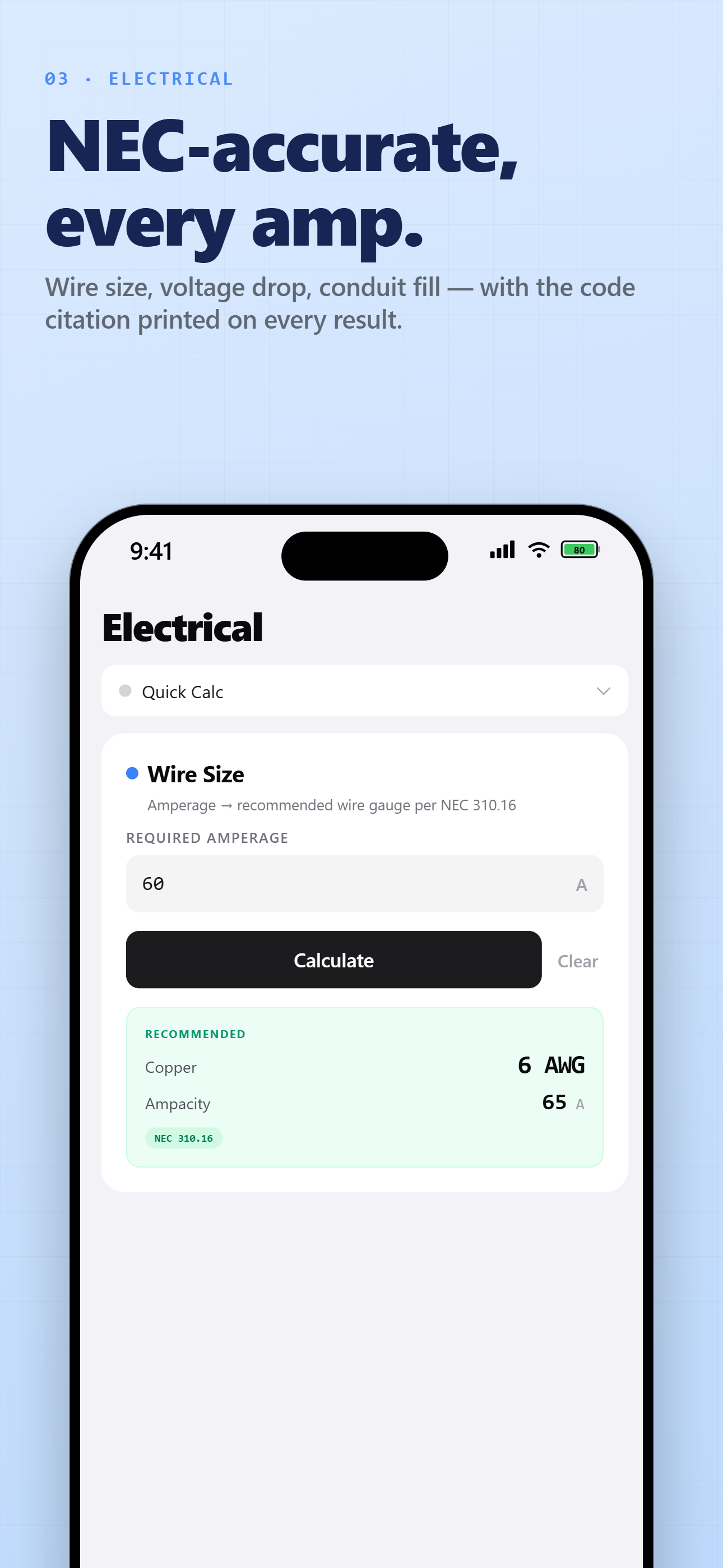
Wire sizing and voltage drop are the two calculations electricians run on almost every job. Getting them wrong means failed inspections, tripped breakers, and in the worst case, fires. The process is always the same two checks: pick a conductor with enough ampacity under NEC Table 310.16, then confirm the run is short enough that voltage drop stays inside the NEC’s 3% and 5% recommendations. This guide walks through both checks with the actual table values and formulas, a copper-vs-aluminum comparison, a full 200 A service worked example, and answers to the questions electricians actually search for.
Verify before you build. Section numbers, table values, and demand factors change between code editions, and jurisdictions adopt them with local amendments. Treat this guide — and the app — as a calculation aid, not as the code book: confirm every number against the edition your authority having jurisdiction enforces. How FieldDojo validates its calculations.
What Size Wire Do I Need? Start With NEC Table 310.16
Wire size is determined by ampacity — the maximum current a conductor can carry continuously without exceeding its temperature rating. NEC Table 310.16 — Table 310.15(B)(16) in pre-2020 editions — is the go-to reference for most residential and commercial work.
Key inputs:
- Breaker/load amperage
- Conductor material (copper vs aluminum)
- Conduit type (PVC, EMT, free air)
- Temperature rating (60°C, 75°C, 90°C)
- Number of current-carrying conductors (derating applies at 4+)
Here are the 75°C copper values (THWN/THHN insulation) for the sizes you’ll reach for most often, plus the circular-mil areas you’ll need later for voltage drop:
| Gauge | 75°C Ampacity (Cu) | Max Breaker per 240.4(D) | Circular Mils |
|---|---|---|---|
| 14 AWG | 20 A | 15 A | 4,110 |
| 12 AWG | 25 A | 20 A | 6,530 |
| 10 AWG | 35 A | 30 A | 10,380 |
| 8 AWG | 50 A | — | 16,510 |
| 6 AWG | 65 A | — | 26,240 |
| 4 AWG | 85 A | — | 41,740 |
| 3 AWG | 100 A | — | 52,620 |
| 2 AWG | 115 A | — | 66,360 |
| 1 AWG | 130 A | — | 83,690 |
| 1/0 AWG | 150 A | — | 105,600 |
| 2/0 AWG | 175 A | — | 133,100 |
| 3/0 AWG | 200 A | — | 167,800 |
| 4/0 AWG | 230 A | — | 211,600 |
Source: NEC Table 310.16, 75°C copper column; breaker caps from NEC 240.4(D).
Why Does a 30 A Breaker Need 10 AWG If 10 AWG Is Rated 35 A?
The familiar 15/20/30 A pairings for 14/12/10 AWG copper aren’t ampacities from Table 310.16 — they’re the maximum overcurrent limits NEC 240.4(D) puts on small conductors. 10 AWG copper really is rated 35 A at 75°C, but the breaker protecting it can’t exceed 30 A. For 8 AWG and larger, no small-conductor cap applies and the 75°C ampacity governs directly. Always size on whichever number is lower — the breaker sizing guide covers the load-side arithmetic and the 240.4(B) next-size-up allowance.
Which Temperature Column Should I Use?
Table 310.16 has three columns: 60°C (TW, UF), 75°C (THWN, THHN, XHHW), and 90°C (THHN, XHHW-2). Ampacity is limited by the lowest-rated termination in the circuit, and most breakers and devices are rated for 75°C terminations — so the 75°C column is the practical standard even when the insulation on the wire is rated 90°C. If your terminations are rated 60°C, common on older panels, the 60°C column governs.
Derating for Multiple Conductors
When more than 3 current-carrying conductors share a raceway, NEC 310.15(C) requires an adjustment to the table ampacity:
| Current-Carrying Conductors | Adjustment Factor |
|---|---|
| 4–6 | 80% |
| 7–9 | 70% |
| 10–20 | 50% |
| 21–30 | 45% |
| 31–40 | 40% |
| 41+ | 35% |
This is where many calculations go wrong. A circuit that’s adequately sized for ampacity alone can fail the derating check. Separately, NEC 310.15(B) requires ambient temperature correction when the surroundings exceed 30°C (86°F) — summer attic runs are the classic case.
How Much Voltage Drop Is Allowed?
The NEC doesn’t mandate a maximum voltage drop. Two informational notes recommend:
- 3% maximum for branch circuits — NEC 210.19(A)
- 5% maximum total from service entrance to the final outlet — NEC 215.2(A)(4)
These are Fine Print Notes, not enforceable code — but most jurisdictions and inspectors treat them as de facto requirements, and an undersized long run shows up later as dim lights, warm conductors, and callbacks.
How Do You Calculate Voltage Drop?
The single-phase formula:
VD = (2 × K × I × D) / CMWhere:
- VD = voltage drop (volts)
- K = resistivity constant: 12.9 for copper, 21.2 for aluminum, at 75°C operating temperature
- I = load current (amps)
- D = one-way length of the circuit (feet)
- CM = circular mils of the conductor, from NEC Table 310.16
The factor of 2 accounts for the round trip — current travels out on the hot and back on the neutral. As a percentage:
VD% = (VD / source voltage) × 100Example: 20 A circuit, copper, 100 feet one-way, 120 V, 12 AWG (6,530 CM):
VD = (2 × 12.9 × 100 × 20) / 6,530 = 7.9 V → 6.6% ✗6.6% blows past the 3% recommendation. Upsize to 10 AWG (10,380 CM):
VD = (2 × 12.9 × 100 × 20) / 10,380 = 4.97 V → 4.1% ✗Still over. Try 8 AWG (16,510 CM):
VD = (2 × 12.9 × 100 × 20) / 16,510 = 3.12 V → 2.6% ✓The Shortcut: Solve for Circular Mils Directly
Instead of iterating gauge by gauge, solve for the minimum conductor once:
VD_max = source voltage × (max drop % / 100)
CM_min = (2 × K × I × D) / VD_max
For the circuit above: VD_max = 120 × 0.03 = 3.6 V, so CM_min = (2 × 12.9 × 20 × 100) / 3.6 = 14,333 CM. From the table, 10 AWG (10,380 CM) is too small and 8 AWG (16,510 CM) is the first size that clears — same answer, one calculation. Then confirm the winner’s ampacity still covers the load.
Two assumptions worth knowing: K = 12.9 corresponds to copper at 75°C (the constant varies with temperature — copper is 10.37 ohm-cmil/ft at 20°C), and the formula assumes unity power factor, so heavily reactive loads see somewhat more drop.
What About Three-Phase Circuits?
For three-phase, the round-trip factor 2 becomes √3:
VD = (√3 × K × I × D) / CMThat cuts voltage drop by about 13% versus single-phase for the same wire and distance.
Copper vs Aluminum Wire: What’s the Difference?
| Factor | Copper | Aluminum |
|---|---|---|
| Resistivity constant (K) | 12.9 | 21.2 |
| Ampacity per gauge | Higher | ~78% of copper |
| Size for the same ampacity | Baseline | 1–2 gauge sizes larger |
| Weight | Heavier | ~30% of copper’s weight |
| Cost | Higher material cost | Lower material cost, higher labor |
| Connections | Standard terminations | Anti-oxidant compound, torque specs |
| Typical use | Branch circuits, all sizes | Service entrance, larger feeders |
The K values feed straight into the voltage drop formula: at K = 21.2 versus 12.9, an aluminum conductor of the same circular-mil area drops roughly 64% more voltage than copper. That’s why aluminum runs get sized up — usually one to two gauge sizes — and why it earns its keep mainly on service entrance cable and large feeders, where its weight (about 30% of copper’s) and lower material cost outweigh the bigger conduit and the termination rules. Aluminum lugs need anti-oxidant compound and specified torque; skip either and you’ve built a heat problem into the wall.
Worked Example: A 200 A Service, 180 Feet Out
Say you’re feeding a detached shop: 240 V single-phase, 200 A, 180 feet one-way from the service equipment, copper conductors, 75°C terminations, 3% drop target.
Step 1 — Ampacity. From NEC Table 310.16 at 75°C, 3/0 AWG copper is rated exactly 200 A. That’s the ampacity floor.
Step 2 — Voltage drop target.
VD_max = 240 V × 0.03 = 7.2 V
CM_min = (2 × 12.9 × 200 × 180) / 7.2 = 129,000 CM
Step 3 — Reconcile both constraints. 2/0 AWG (133,100 CM) clears the 129,000 CM drop requirement — but at 175 A (Table 310.16, 75°C) it fails the 200 A load. 3/0 AWG passes both: 200 A ampacity and 167,800 CM.
Step 4 — Verify the actual drop with 3/0:
VD = (2 × 12.9 × 200 × 180) / 167,800 = 5.54 V
VD% = 5.54 / 240 = 2.3%   ✓
Here ampacity governed, not distance. Stretch the run far enough and the constraints flip: CM_min grows with every foot until voltage drop, not ampacity, picks the conductor. Run the same feeder in aluminum (K = 21.2) and CM_min jumps to 212,000 CM — just past 4/0 AWG (211,600 CM), so the first standard size that clears the drop target alone is 250 kcmil (250,000 CM). And that’s before checking aluminum’s ampacity column, which runs about 78% of copper’s at every gauge.
Common Wire Sizing Mistakes
1. Using the wrong temperature column. If your terminations are rated 60°C (common on older panels), you must use the 60°C ampacity column — even if the wire and conduit are rated for 75°C.
2. Forgetting derating. Bundled conductors run hotter. Pull 6 circuits through one conduit and your effective ampacity drops to 80% of the table value per NEC 310.15(C).
3. Not accounting for both legs on voltage drop. The formula uses 2 × D because current travels down and back. Forgetting to double the length understates voltage drop by half.
4. Using K = 11 for copper. Some older references use 11; the more accurate value is 12.9 at 75°C. The difference matters on long runs.
5. Upsizing for voltage drop and leaving the ground alone. When the phase conductors go up a size for voltage drop, NEC 250.122(B) requires a wire-type equipment grounding conductor to go up in proportion — see the ground wire sizing guide.
6. Treating aluminum like copper. Same gauge, different conductor: K = 21.2 versus 12.9 means far more drop per foot, and lower ampacity per gauge means an aluminum swap is never one-for-one.
Frequently Asked Questions
How do I size wire for a 100 amp sub panel?
In the 75°C copper column of NEC Table 310.16, 3 AWG copper is rated exactly 100 A. Aluminum feeders land one to two gauge sizes larger for the same rating. Then check voltage drop: on a long run to a detached garage, the 3% recommendation (NEC 210.19(A)) often forces a size beyond the ampacity minimum.
What size wire do I need for a 50 amp breaker?
8 AWG copper carries 50 A in the 75°C column of NEC Table 310.16, and the NEC 240.4(D) small-conductor caps stop at 10 AWG, so nothing limits the breaker below the ampacity. If your cable or terminations are rated 60°C, that lower column governs and typically pushes you up a size. Check voltage drop on long runs.
What size wire for a 30 amp breaker?
10 AWG copper. Its 75°C ampacity in Table 310.16 is actually 35 A, but NEC 240.4(D) caps the breaker protecting 10 AWG at 30 A, and that cap is the binding constraint. The same rule pairs 12 AWG with 20 A breakers and 14 AWG with 15 A breakers.
How far can you run 12 AWG wire on a 20 amp circuit?
About 45 feet one-way at full load on 120 V before crossing the 3% recommendation: rearranging the formula, D = (3.6 V × 6,530 CM) / (2 × 12.9 × 20 A) ≈ 45 ft. A lighter actual load or a 240 V circuit stretches that; a full 20 A at real distance means 10 or 8 AWG.
Can I use the 90°C column for THHN wire?
Usually not. THHN insulation is rated 90°C, but ampacity is limited by the lowest-rated termination in the circuit, and most breakers and devices are rated for 75°C. That makes the 75°C column of Table 310.16 the practical standard for residential and commercial work, even with 90°C wire in the raceway.
Is voltage drop an NEC requirement?
No — the 3% branch-circuit figure (NEC 210.19(A)) and the 5% service-to-outlet figure (NEC 215.2(A)(4)) are informational notes, not enforceable code. In practice, most jurisdictions and inspectors treat them as requirements, and a run that ignores them shows up later as dim lights, warm conductors, and callbacks.
How FieldDojo Handles This
Everything above is table lookups and one formula, applied in the right order — exactly the kind of work a phone should do while you’re standing at the panel. FieldDojo’s wire sizing calculator takes your load amps, one-way distance, voltage, and conduit type; pulls the 75°C ampacities from NEC Table 310.16; applies the 240.4(D) caps on 14, 12, and 10 AWG; derates per 310.15(C) when you specify more than three current-carrying conductors; and runs the voltage drop math for every candidate gauge before returning the smallest compliant size with its drop percentage. Every result carries the NEC table and section number it came from, so the calculation holds up when the inspector asks where a number came from.
Get FieldDojo on the App Store → or on Google Play → — free on both.
Related trade guides: